Where's This Train Going?
I’m currently reading Julian Havil’s book Curves for the Mathematically Curious. The chapter on Euler’s spiral (which I’ve always known as the Cornu spiral) had a comment which reminded me of my days at Applicon.
Imagine you’re laying railroad tracks and have to make a 90 degree turn. How exactly do you do that? If you remember playing with model railroads as a child, it seems easy. You take some straight sections, then add enough arc sections to add up to 90 degrees. Then you go back to straight sections. But that’s not how you do it on a real railroad. The reason has to do with something called continuity.
Let’s imagine we’re riding on that model railroad you built, and calculate what it would feel like. In particular, what are the side forces you would feel? Obviously, when the train is on a straight section, there aren’t any side forces. And almost as obviously, when it’s on an arc section, there’s a constant side force which is proportional to the radius of the arc. But when the train goes from a straight to an arc (or from an arc to a straight), the force changes suddenly. If you’re standing up while riding the train, that sudden change is going to make you stumble.
This is all simple calculus. When the train moves sideways (as in turning a corner), the first derivative of the position is called velocity. The second derivative is called acceleration. That’s the side force you feel. The second derivative is called jerk. Really! The next 3 derivatives are called snap, crackle, and pop. Who said engineers don’t have a sense of humor?
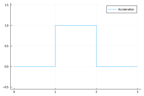
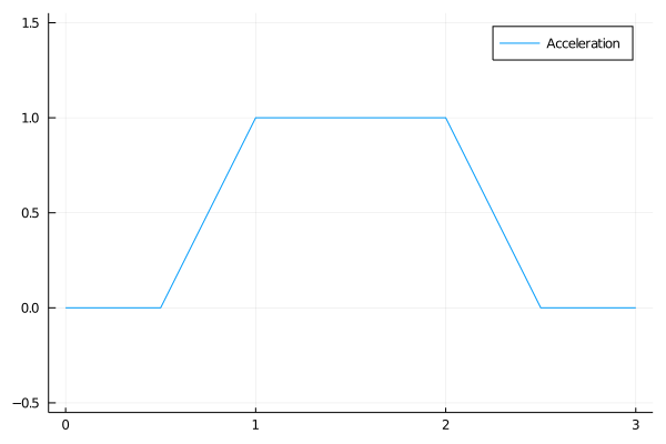
A mathematician would say that your model railroad is C1 continuous. That means that there isn’t a discontinuity in position or lateral velocity, but there may be in the acceleration. To have a nice smooth ride, we’d like to keep the jerk small, which means you want at least C2 continuity.
The way that’s done in practice is using the lovely Cornu spiral as a transition between the straights and the arcs. This spiral has the interesting property that the radius of curvature changes linearly as you move along the curve. That means that it is possible to stick in a transition piece which will make the side force smoothly ramp up from nothing on the straight section to the acceleration of the arc.
The resulting corner looks something like this:
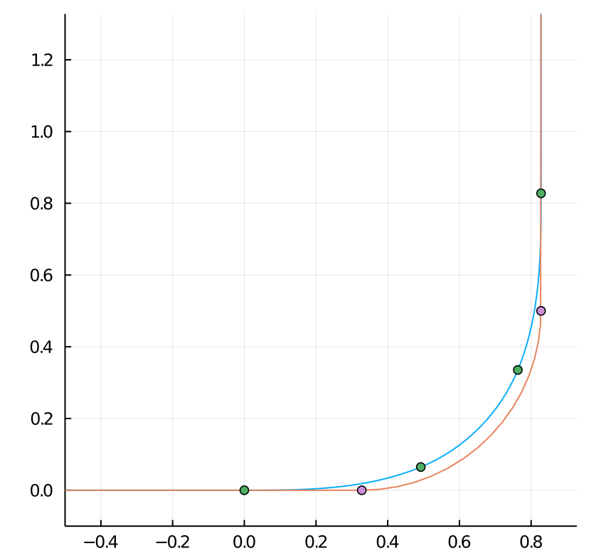
The red curve is our model railroad with the sudden transition from straight to arc. The blue curve is uses sections of Cornu spirals to transition between them. The radius of the arc is the same in the two curves, but the blue one would feel nicer if you were riding on the train. The markers show where the segments join.
Computing this shape is actually rather tricky. It involves something called Fresnel integrals. Here’s a simple Julia script that shows how it works. There is actually a lot of other interesting math involved in designing real railroad lines. This AREMA presentation does a nice job of explaining many of the issues.
But what’s all this got to do with Applicon? They didn’t design railroad tracks. Actually, many of our biggest customers at Applicon were car companies, and it turns out you hit a lot of these same issues when you are designing car bodies. Because cars have such shiny paint jobs, discontinuities in the higher derivatives are very obvious in the reflections. That meant that to keep these customers happy, we needed to ensure that it was very easy for a designer to get at least C2 continuity when they were using our system to design car bodies. We did this with NURBS instead of Cornu spirals, just because the math is simpler.
We also did a rendering mode which showed up what your model would look like if it was polished and placed in a room with stripes or checkerboards on the wall so that you could see any continuity issues. The result was kind of trippy looking, but it was very good at highlighting issues before the user fabricated the shape.